FJITA: The Project that Just Wasn't Meant To Be
Common wisedom says to not give up. But nevertheless sometimes, that seems to be exactly the right thing to do.
Project FJITA (no, I will not explain what the acronym means) was an interesting idea that originated in 2007. Back then, I became interested in the lower-level details of DVDs. I had build a hardware hack that allowed me to capture the raw bitstream from DVDs, and wrote a software decoder for DVD bitstreams. I used this setup to figure out how the optical media authentication for Gamecube and Wii games worked, and since ever, I was curious - for the sake of science, of course! - how hard it would be to produce compatible discs. For example, if someone cuild build a self-booting Linux disc for Gamecube that would have been awesome. (I’m not encouraging to do this with any commercial games, of course.)
But let’s go back one step and take a look at what traditional custom DVD formats sometimes do:
- Non-standard filesystems / ISO9660 contents. For example, the GameCube uses a custom filesystem format, and there are tools like gcfuse that allow working with it. For now, let’s just ignore this. We just treat the disc as a block of data, i.e. an integral number of 2048 byte-sized sectors.
- Non-standard sector data frames. ECMA-267 (and others) describe how the 2048 payload bytes per sector are encoded into frames, scrambled, interleaved into ECC blocks, and then modulated into a bitstream. Different modifications can be done here - the GameCube disc format for example places the payload slightly differently (skipping
CPR.MAI, the 6 bytes directly in front of the user data, which is used for Copy Protection control; this includes the flag for CSS that makes a sector readable only after authentication), uses different scrambling seeds. (Other disc formats also mess with the sector address encoding, though that will actually affect the lower layers as well as the data is used to position the laser when reading the disc.) - This also includes “bad blocks” which are really just sectors that are intentionally stored in an incorrect way - for example with invalid PI/PO data, or an invalid error detection code. Readers are usually designed to ignore such information.
- A disc doesn’t consist only of data sectors, but there are also a “lead-in” and “lead-out” zone, which contains additional data stored in the control data zone (
PFI- Physical Format Information, which contains essential information how to read the data,DMI- Disc Manufacturing Information, where the disc manufacturer can add special data that is not specifically used in standard DVDs etc.). - There may be a Burst-Cutting Area added - a “barcode” (unrelated to the IFPI barcode in the middle ring) containing up to 188 bytes of information.
- The physical sector placement - i.e. the angular position of a sector header, relative to some other property - may be relevant. This can be indirectly obtained by the reader by measuring the delay from seeking to a known start position to the sector-under-test, modulo the rotational rate.
- Custom Wobble encoding can be used to store information; the most well-known example is the original Sony Playstation, which uses this method for copy protection.
- There could be additional information in the channel bitstream that is either ignored by the reader (using error correction), or decoded specifically (such as a DC-balance covert stream)
In a closed system, it’s feasible to design a completely custom disc format of course, but people aren’t too keen on re-implementing the wheel disc; for example,
it may be useful to re-use existing building blocks, be it at the disc mastering, disc manufacturing, development and mass-production of the disc reader.
If - for example - the DVD format is followed to a certain extent, it may be possible to re-use a reader chipset and get away with only (or mostly) software modifications, and does not require to develop a new ASIC from scratch.
Further, optical disc formats are very fine-tuned to actual physics. For example, the way how tracking is achieved: after all, a DVD has a track pitch of 740nm, meaning that the tracks are only 740nm apart(!). These tracks need to be accurately followed by the pickup assembly when reading the data, with a device that may costs $15 or less in mass-production. There is no place for high-quality optics, fine-tuned mechanics or anything like that. Instead, the hardware cost is reduced to the greatest possible extent, and instead sophisticated control loops are implemented in software (and silicon).
This places a limit on what properties can be measured. For example it’s not possible to measure the track-to-track pitch variations accurately. Designing a disc authentication format that relies on track pitches being accurately measured would increase the cost of the reader significantly.
For the purpose of creating discs, this is great news - because it means that there’s somewhat a symmetry between creating and validating the discs - it doesn’t make sense to produce a feature that can’t be verified with a standard (in terms of hardware) reader. As an extension of that, features that can be verified by a cheap reader can - with some exceptions - be also produces with a cheap writer. I know, I know - it’s not that easy. Writers for home-use (i.e. regular DVD+RW drives etc.) are designed to only write standards-compliant discs.
And this is where Project FJITA started: The attempt to modify a stock CD/DVD/BD writer to write custom discs. Sounds crazy? Let’s take a closer look at the properties we need to customize:
| Property | Stock Writer | |
|---|---|---|
| Non-standard filesystem | ✅ | We can burn arbitrary (non-).ISO files |
| Non-standard data frames | Writer encodes 2048-bytes to sectors, can’t pass raw sectors | |
| Bad Blocks | Writer always produces valid blocks | |
| Non-standard control frames | Only very indirect control over control frames | |
| Burst-Cutting Area | No | |
| Angular position of sector headers | Can’t influence layout | |
| Wobble | No | |
| Bitstream modifications | No |
The first one is easy to achieve - just pre-produce a custom ISO image (which is not actually ISO9660 anymore at that point…), and burn that with a tool that doesn’t attempt to verify it first. However, that’s as far as we can go with a “regular” firmware.
Writing non-standard data frames can easily be done for CDs when writing; it’s possible to write with “2448 bytes per sector” (RAW/DAO96R), which means that the task of encoding the 2048 bytes of a logical sector into a physical frame is left to the host. This allows writing Audio CDs (with arbitrary subchannel data), but for CD-ROM Mode 1 data, this allows custom (inner) ECC (error correction code) and EDC (error detection code) data as well. This can also be used for inserting arbitrary bad blocks. (I took great pride in ~2000 when I sold self-burned Data CDs - with self-produced content - with “copy protection”, based on a combination of unreadable sectors (which were checked at runtime) as well as filesystem modifications that prevent copying the individual files; good times… Probably trivial to work around if you knew what you were doing, but most people didn’t.)
Unfortunately for us, such a scheme doesn’t exist for DVDs - it’s not possible to burn, say, 2064 byte blocks (which would include sector information and EDC), or even custom ECC blocks - the minimum addressable data unit on DVDs that the error correction code operates on - or recording frames (the individual parts of an ECC block). It would very likely work with either modified DVD burner firmware, or by using custom commands. Indeed, some DVD burners have vendor-specific commands to write arbitrary frames.
This still doesn’t help us for non-standard control frames, as they are generated by the device itself. However there’s a nice hack that can be done for most firmware:
It’s possible to write “multi-session” DVDs; basically, it’s possible to only write a few user sectors, and later write more user sectors. Dual-layer discs complicate this a bit (they basically split each partition equally to both layers), but in the end, there’s a variable stored in the recorder’s memory that points to the PSN (physical sector number) of the first data sector. By default, this is 030000 - the start of the data zone, which corresponds to a radius of 24mm from the center of the disc. Because this offset is variable (for multi-part writes), it’s stored in RAM. Most firmware has backdoor commands to read/write RAM, so by using such a function (or adding one, if not present), it’s possible to move the data sector to otherwise unsupported values - such as before the actual data zone. For example, by setting this offset to 02F000, it’s possible to write the complete lead-in with user data. The burner will simply format the supplied data into ECC blocks - with PSNs of the lead-in - and write it. (Though there are some control bits in the address information field that indicate if this is lead-in or data area, they are mostly ignored.)
It’s not a great way, but it’s simple. It allows to write specific lead-in data with only very simple modifications to the firmware (usually not even persistent, just by poking in RAM with vendor-specific commands).
| Property | Stock Writer | Firmware hackery | |
|---|---|---|---|
| Non-standard filesystem | ✅ | ✅ | Just feed custom data |
| Non-standard data frames | ✅ | Custom firmware “WRITE LONG” | |
| Bad Blocks | ✅ | Same - just “WRITE LONG” invalid frames | |
| Non-standard control frames | ✅ | “Start PSN” hack lead-in/lead-out | |
| Burst-Cutting Area | No | ||
| Angular position of sector headers | No | ||
| Wobble | No | ||
| Bitstream modifications | No |
It’s not perfect, but it’s a start. It’s not sufficient to produce a GameCube disc that would pass verification, though, we need more - specifically we need to write a BCA, and we need to produce the “laser cuts”.
This cannot be done - as far as I know - by just software hacks on the DVD burner, as the encoding of the data itself is done in hardware. So how do we create such discs?
We could go and dive into physics, and build our own mastering equipment, with a high-quality laser that somehow inserts pits and lands with sub-micrometer accuracy.
Or we could cheat and just use a stock burner, and be clever!
Introducing: FJITA
The core idea of this project is to Man-In The Middle the communication between the ASIC/DSP and the optical pickup head (OPU); we would then write a full disc with dummy data, but instead of using the DSP-generated bits to drive the laser, we would supply our own bitstream.
Let’s first quickly describe how a DVD burner operates - as described it’s unfeasible to operate open-loop, i.e. by just positioning the laser without position feedback. There is simply no way to position the sledge accurately enough to hit the desired track pitch.
- Positioning: We need coarse but absolute positioning on the disc, so that the data track can start at 24mm.
- Tracking: We need to accurately move the sledge by 740nm per revolution, +/-30nm.
- Focus: We need to keep the laser spot size as small as possible, but definitely <740nm.
- Linear velocity: We need to write the bits at exactly the right rate; while the long-term inaccuracy doesn’t matter as much, short-term variations must be kept small to avoid the reader PLL losing lock.
- Tilt (but let’s ignore this for now)
So how does a writer solve these issues? Interestingly in pretty much the same way as a reader. A reader solves this by locking to the track - it uses an array of photodiodes to detect how much light is reflected. Because it uses not just one photodiode, but multiple, it can figure out if the laser illuminates the disc in the right way (i.e. as a nice focused spot in the center of the track), versus how much light is reflected mis-aligned (tracking) or out of focus. For more details, here is a document describing some of the details, but this is relatively standard since CDs were introduced in the 1980s.
But a writer writes the track, so how can it follow one? It’s a trick question - the answer is that blank, writeable discs are manufactured to already include a track, a so-called pre-groove. The pre-groove is followed while writing the data track to the disc; it is ignored at readout because it’s much smaller (signal-wise) than the data itself.
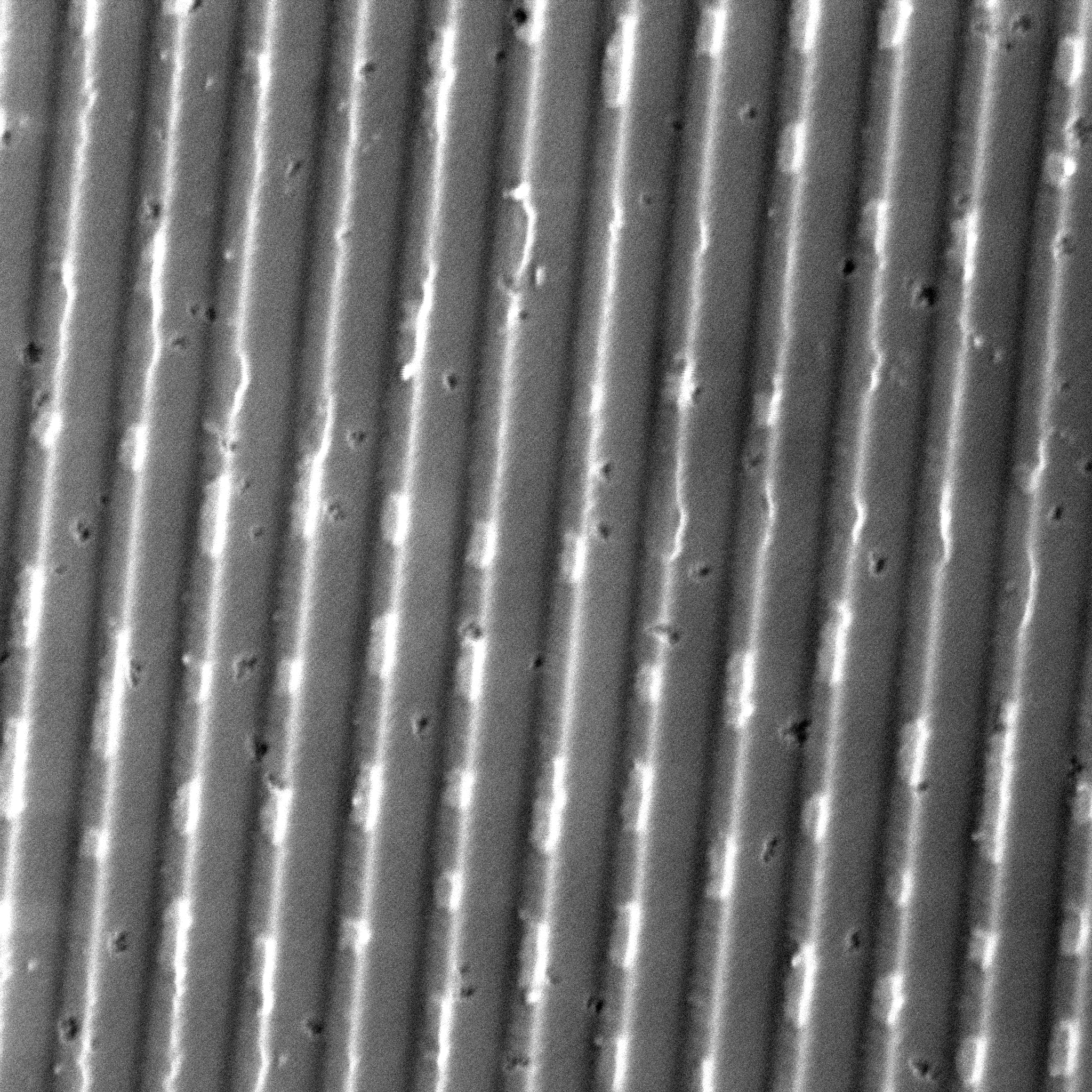
The pre-groove solves tracking and focus while writing - the writer can use the reflected light from the pre-groove for a closed tracking (radial positioning) and focus (distance from disc) loop, and get to the required nanometer relative positioning. But it doesn’t solve the absolute positioning and linear velocity - yet.
For that, the trick is to add information to the pre-groove; the exact scheme varies slightly beween technologies (CD-R, CD-RW, DVD-R, DVD+R, DVD+RAM, BD-R) but the general idea is that the pre-groove is modulated in some sort to add data to it. This can be done for example by wobbling the pre-groove a tiny bit. The movement is too fast for the head to follow (there’s a cutoff frequency in the control loop), and small enough that it doesn’t actually disturb the decoding, but a special circuit can pick up the modulation, and decode the data. The data includes the absolute address (hence this is called ATIP - absolute time in pre-groove for CDs, or ADIP - Adress in pre-groove for DVDs), but also allows the writer to track the exact speed of the medium, much more accurately and precise than what would be possible by maintaining the rotational rate (from the motor) alone.
But this also means that a writer cannot freely write on the disc - it always needs to follow the pre-groove. We can’t change the track pitch while following the pre-groove. But not following the pre-groove would mean we would need expensive accurate equipment to position the laser.
At first, this seems bad news. For example, if we want to burn a burst-cutting area, we need radial stripes, i.e. perpendicular to the usual motion of the laser over the disc. It also doesn’t easily allow for free-form graphics.
Small intersection: BCA
The burst-cutting area is a way to add information to a disc that is generated after the disc has been produced. This allows to use cheap mass-production of discs with a stamper, but still enable serialization, i.e. adding per-disc information.
In a regular setup, the BCA is added with a strong laser that cuts into the aluminum of the disc. To read a BCA, the reader places the pickup over a specific region on the disc - using coarse tracking only - and rotates the disc at a fixed speed. No tracking or velocity tracking is used (but focus must be achieved either way), and a special circuit collects the bits.
The information density is relatively low; it’s only possible to store 188 bytes on a disc with this technique.
So do we need to build a laser jig to burn these cuts? The surprising answer is “no”. Have you ever noticed the “art” in the middle of a CD? There’s usually a barcode (that is not readable in a CD reader), and sometimes a logo. It’s part of the stamper, and the interesting bit is how that picture is created on the disc:
It’s part of the data! The bitstream is conditionally blanked - critically aligned with the rotational angle - to create this pattern.
This is actually a very nice idea - if we could write arbitrary bitstreams to the disc, we could embed larger structures (such as logos, but also BCA stripes) into the bitstream.
Interestingly, this is (one part of) how Datel worked around the GameCube disc copy protection - they did not burn the cut marks into the discs, but instead included it in the bitstream itself. This allowed them to write them to precisely the right position within the bitstream, i.e. relative to the beginning of the sector. It compromises the absolute position (angular position) on the disc, especially for neighboring tracks, but this doesn’t matter - the reader can’t figure it out either!
So could we use this method to write a BCA to the disc?
MITM
A disc writer for home usage follows the pre-groove, and modulates a high-power focused laser to modify the surface of the disc. A very simple approximation is that enabling the laser will heat up the material, thereby making the otherwise crystalline material amorphous, which changes the amount of reflected light. It’s not exactly pits&lands, but it behaves very similarly during the readout. The laser needs to be modulated very quickly - if we’re writing with 1X (DVD), this would be a rate of 26.15625 MBit/s. Thankfully lasers can be modulated that fast (much, much faster actually in optical communication systems).
But it’s not as easy as switching the laser on and off corresponding with the encoded bits - due to the physical process, the leading and trailing edges needs to be modified to give the best possible edges. This paper describes this better than I could.
The waveform that drives the high-power write laser is not directly generated by the ASIC/DSP. Instead, multiple power levels are configured directly in the laser driver IC, and multiple digital channels - usually 3 or 4 - are used in combination to select the power levels. The exact power levels are determined by test runs - there’s a special area on writable discs that can be used to “train” the process, i.e. to write a pattern, read it back, and analyze the quality; the power levels are then adjusted and the whole process is repeated until sufficient quality is achieved. Naturally the space on the disc only allows for a limited number of such calibration attempts (unless this is re-writable media), but this would only affect if you’d write to the same disc too many times.
The configuration of the power levels is done over a slow data channel, usually SPI or I2C. The selection of the current laser power is done over 3 (or 4) very fast data channels, usually LVDS channels; for each channel that is driven with a high signal, the configured power is added to the total laser power, so
This enables to use a few digital channels to drive the required waveforms. This is also where this project taps in - by re-directing this bus to an FPGA, and replacing some of the included data with our own data. We’re doing a man-in-the-middle attack on this!
The nice part is - at least in theory - that the writer can continue its normal business. We will wait until the writer has done all the required media selection, calibration, maybe wrote a few sectors - and only then we flip the mux to inject our own data. The writer - again, in theory - would use the regular tracking and focus mechanisms, follow the track, control the spindle speed loop, and all we replace is the data.
By injecting the right data, we can now write arbitrary data to the disc!
In practice, the data has been encoded into a bitstream before using a regular C tool, as encoding is somewhat complex and I didn’t feel like implementing this on an FPGA. The generation of the “write strategy”, i.e. producing the right pulses to produce the right pattern on the disc, is done in the FPGA, based on a lookup table for all valid pulse combinations. Some write strategies need a bit of history, so this is implemented in the FPGA as a shift register, some cobinatorial logic, and a lookup table. The lookup table procudes the 4-channel LVDS stream at 8 to 16 times the bitstream speed. At 4X (4x26.15625 MBit/s=104MBit/s) this is already 837 MBit/s (for each of the 4 LVDS channels!).
For fun and profit
| Property | Stock Writer | Firmware hackery | MITM | |
|---|---|---|---|---|
| Non-standard filesystem | ✅ | ✅ | ✅ | We control all the data |
| Non-standard data frames | ✅ | ✅ | We control all the data | |
| Bad Blocks | ✅ | ✅ | We control all the data | |
| Non-standard control frames | ✅ | ✅ | We control all the data | |
| Burst-Cutting Area | ✅ | Yes, by embedding into data stream | ||
| Angular position of sector headers | ✅ | Yes, by producing the bitstream in the right rate | ||
| Wobble | No | |||
| Bitstream modifications | ✅ | Whatever we want! |
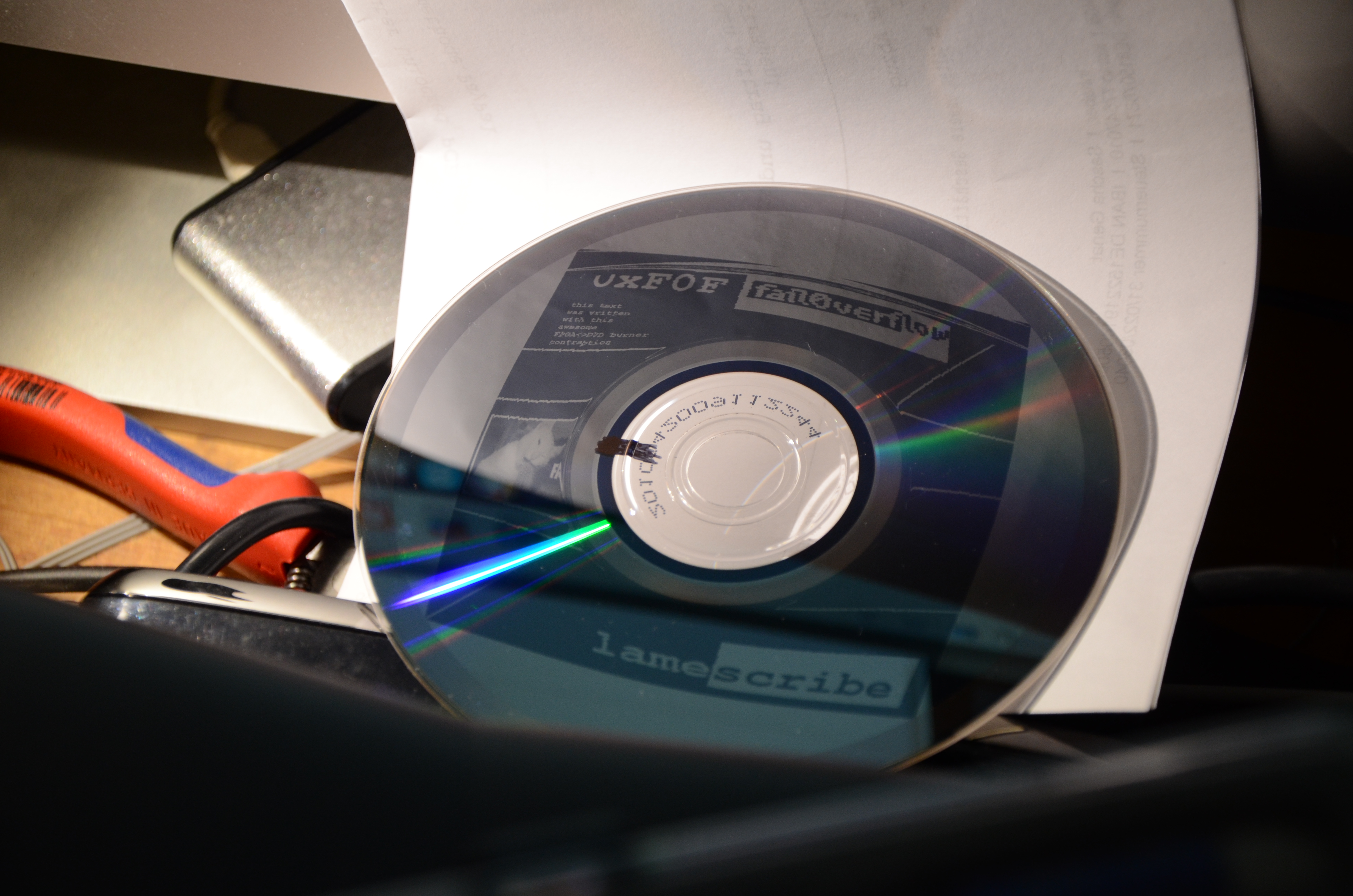
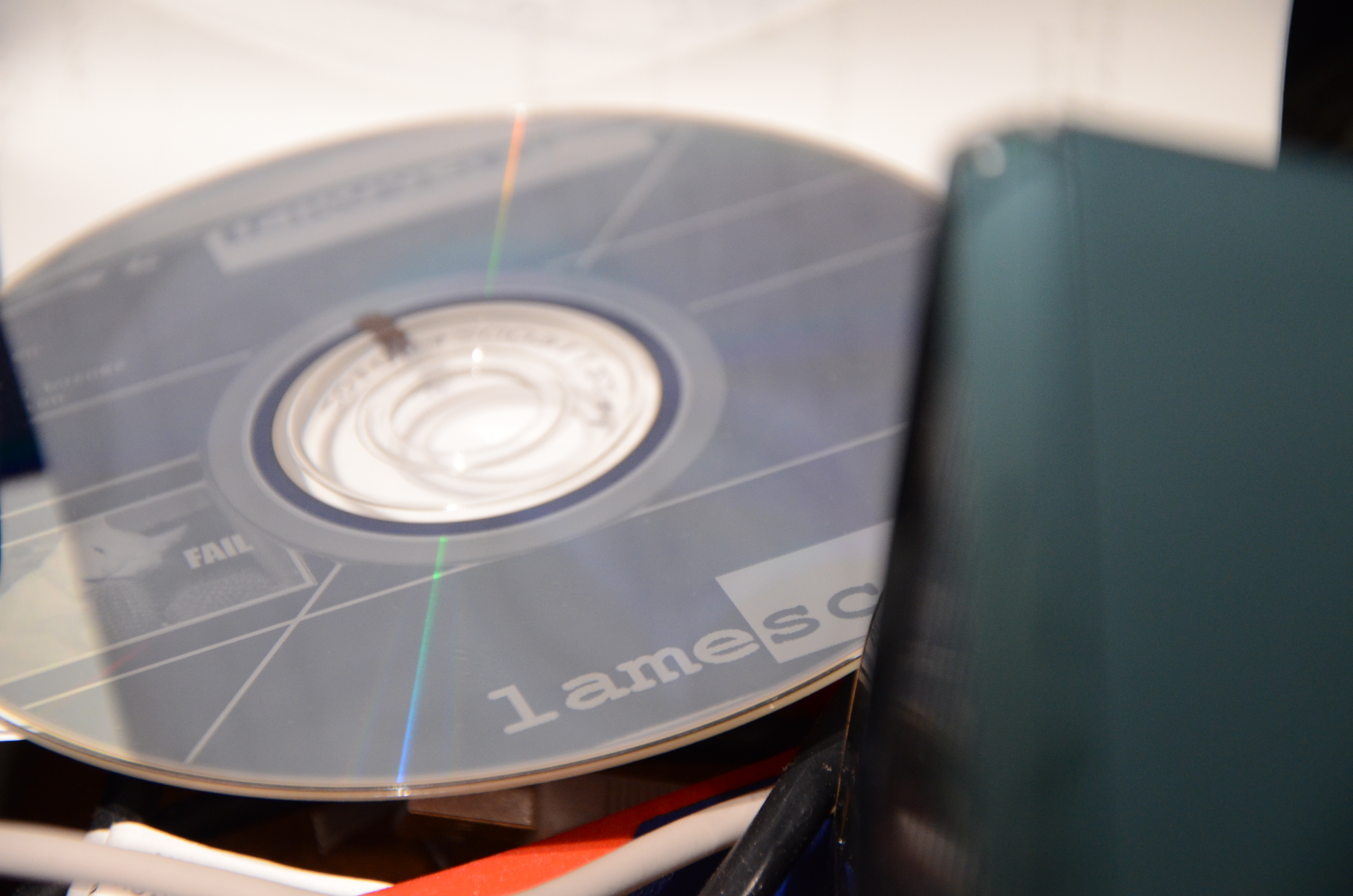
It took me a while, but I was actually able to produce a valid DVD this way.

Fancy!
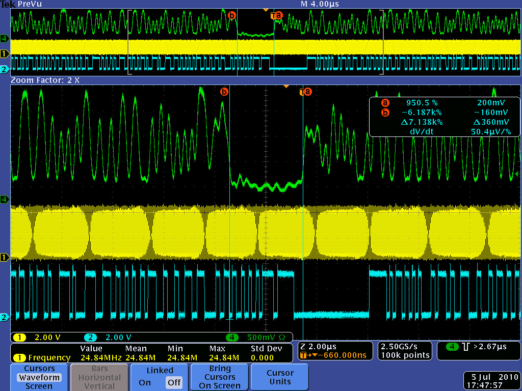
It is possible though to recover the angular position of the disc; initially I did do this with an optical sensor - similar to how LightScribe works, but with a custom marked position on the disc. Later I instead used the so-called FG signal, which drives the spindle motor. (FG is an abbreviation for “Frequency Generator”, which isn’t a very useful description, but it’s the term used in the industry.) This signal yields (usually) 18 pulses per rotation, evenly distributed, and is normally used as a feedback for controlling the rotational speed.
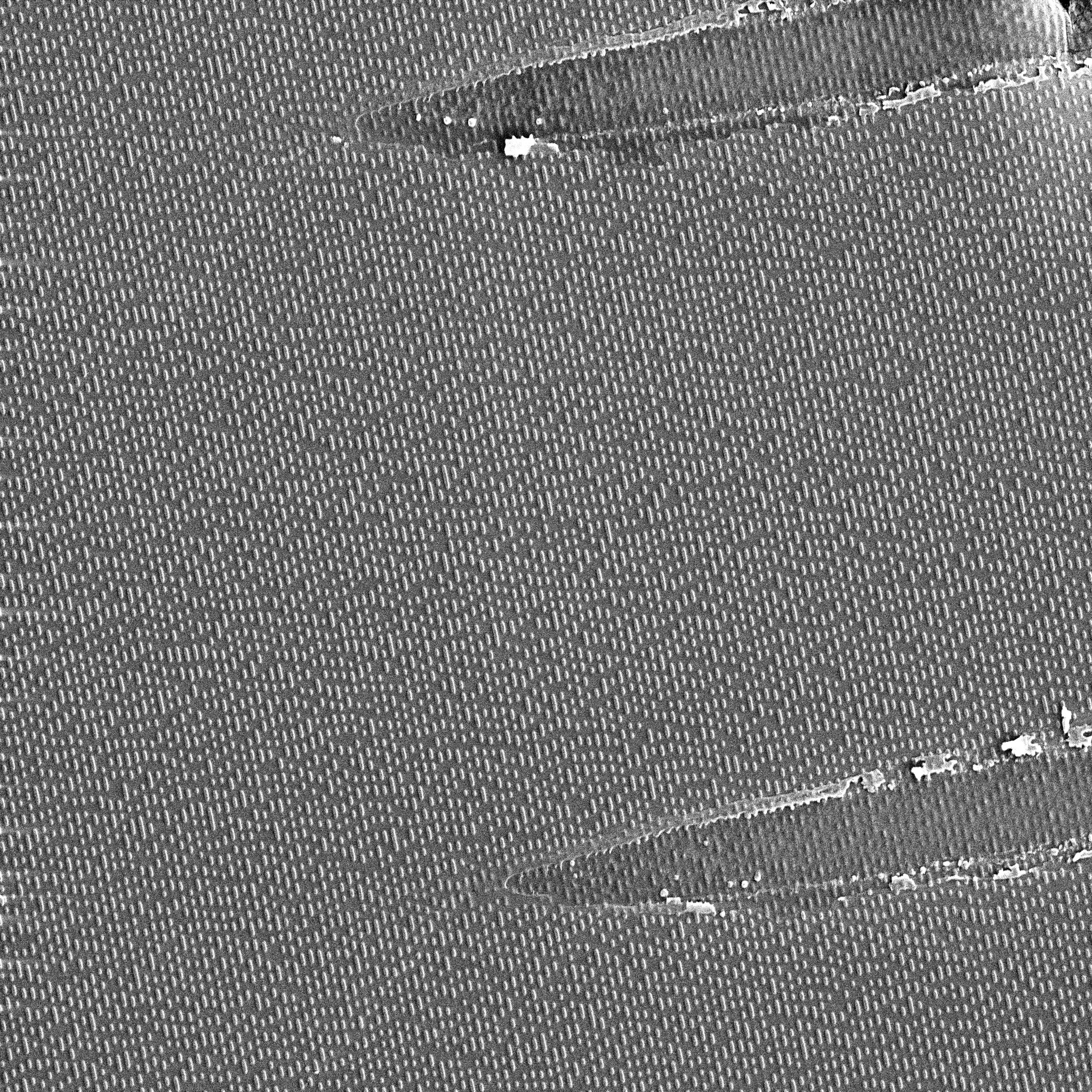
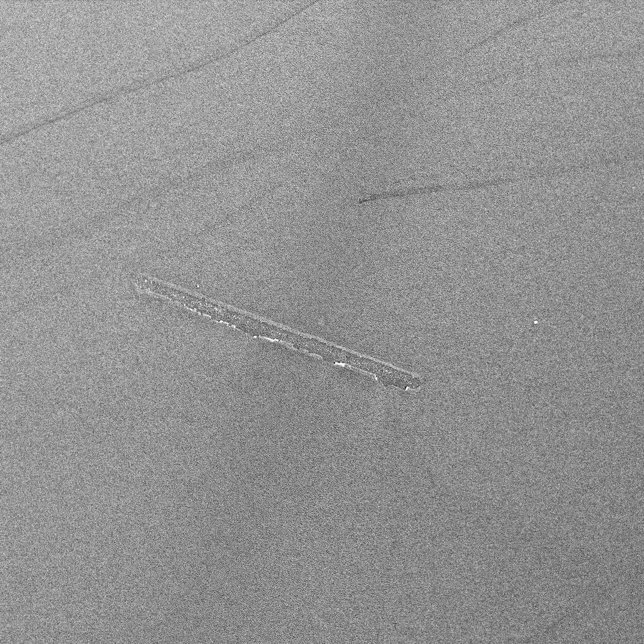
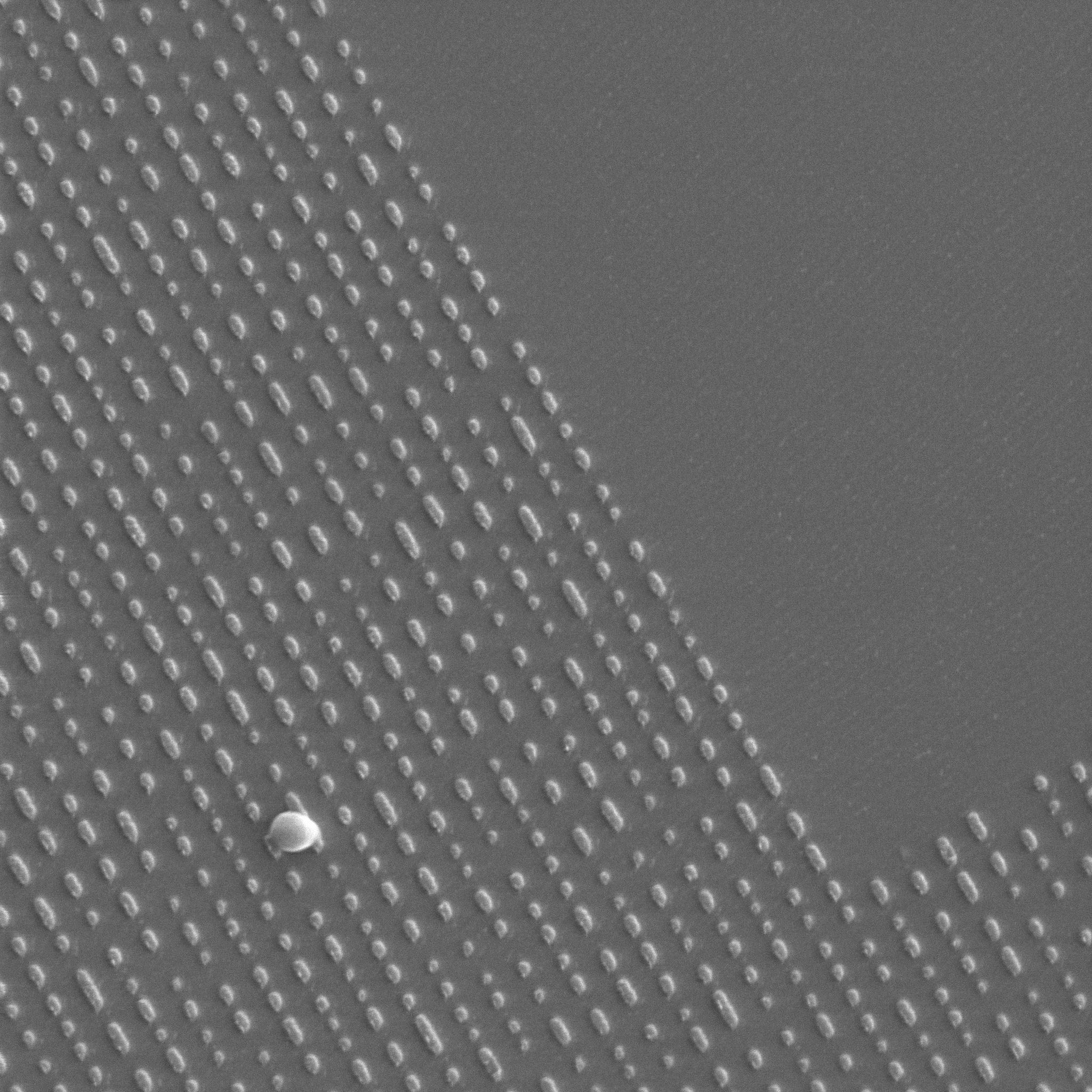
It’s not accurate enough to directly control the signal, but it can be used in a PLL-style arrangement to yield a higher precision position. The total number of rotations (a simple counter), plus the relative position during this rotation (derived from the FG signal) gives the target position in the track. The write speed can be modified by slowing down or speeding up the logical bitstream. Once “lock” is achieved, the relative position of neighbor tracks can be - relatively precisely - pre-computed. This allows us to map arbitrary images onto the disc, as seen in these examples:

In the test picture on the left, a higher-order bit of the virtual position is simply used to blank the bitstream. As you can see (especially in the zoomed original image), the radial jitter is not perfect, but okay(-ish). Further improvements - lowering the FG recovery bandwidth, for example - were possible.
But is it sufficient to use this for a BCA? This could be perceived as a trick question - after all, the reader only reads at a defined radius, so technically the track-to-track alignment of the BCA stripes doesn’t matter… Or does it? It turns out: the reader disables tracking when reading the BCA, so it could be in the middle of two tracks. So yes, it matters. But also - the resolution at some point was good enough.
Encoding BCA
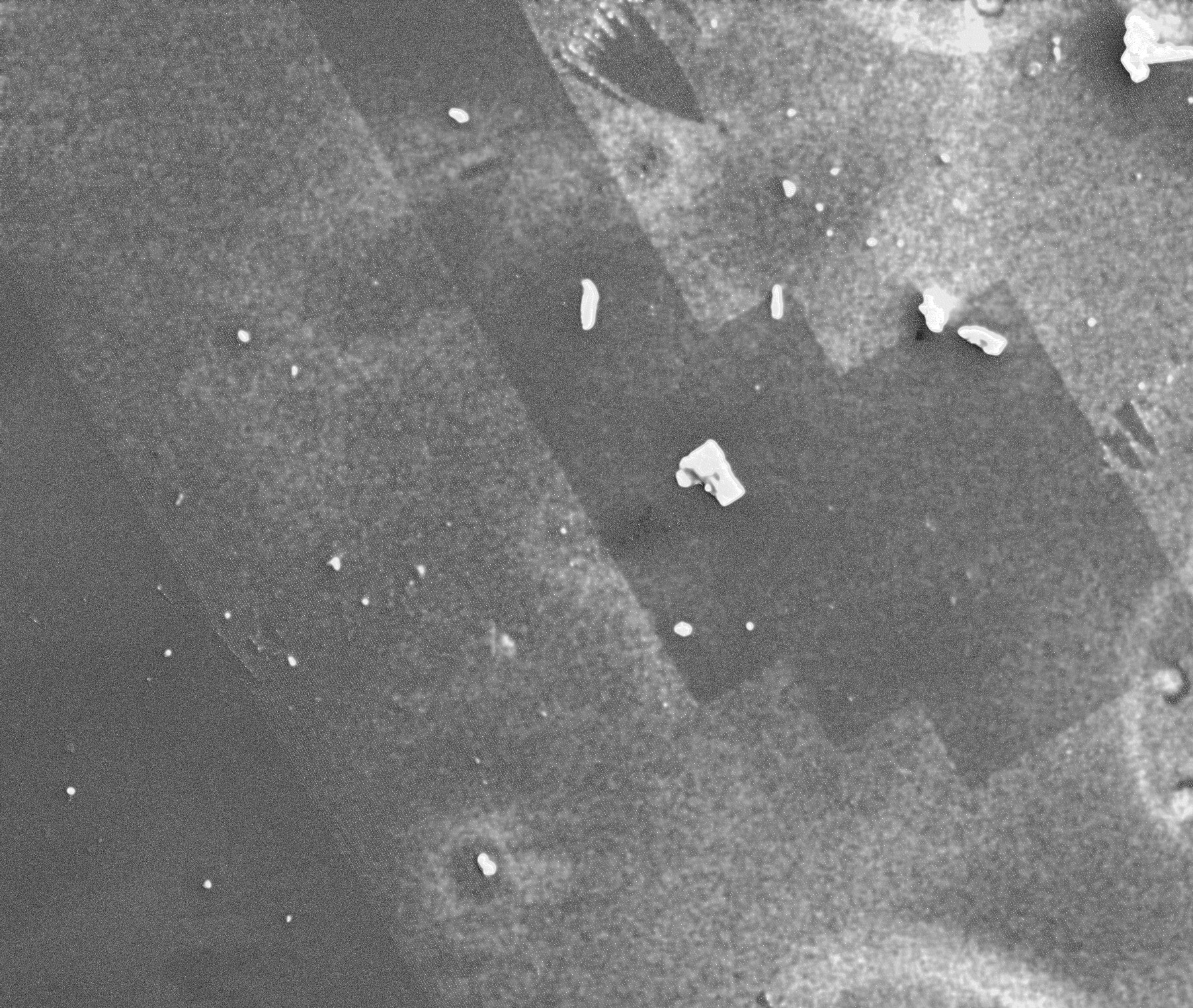
Next step is to actually insert a BCA. This first requires generating the correct data pattern. I did this by using an image of a disc with BCA - provided by marcan, who scanned it - and decoding it optically via software. Once I had written a decoder, I could then write an encoder that worked with my decoder, and encode an arbitrary BCA.

FJITA
We’ve implemented this with a hacked-up NeTV (v1) board; the bitstream was streamed from the SD card into the framebuffer, and the NeTV FPGA (Xilinx XC6SLX9) would then do the conversion to LVDS. We used a BH12LS38 drive, but this was just an arbitrary choice. We hacked up the firmware to allow full access to memory, and hacked up the media table, but nothing major.

fail.
So, did it work? Unfortunately the answer is “no”. Individual parts worked, but we couldn’t ever fix this sufficiently to really work. And the worst is, there isn’t even a good reason. It’s truly a cursed project.
Write Speed
One of the issues is write speed - at 2.4X, with 8X oversampling (for the write strategy), the data is stil manageable. However, 8X oversampling is really tight for higher-speed discs, so at writing at 4X with 16X oversampling, this already results in 1.6GBit/s (per channel), which - unfortunately - reaches the limit of the FPGA (and really our wiring). A valid question is “why don’t just burn at 1X then?”. Unfortunately, modern media does not support it. I had a stash of 2.4X DVD+R discs, but I’ve went through all of them and kind find new ones. All media I could find was 4X minimum. I patched the media tables, but that doesn’t work either - it creates unreadable discs. The issue is that the physical properties for the media are different to allow for the higher write speeds, and that’s not compatible with burning at slower speeds.
APC, WAPC, OPC, ROPC and all that crap
But the thing that really killed this is rooted in a reason that I previously simplified away. The data communication to the laser driver diode is not unidirectional, but bidirectional. While writing, the burner has to constantly monitor the laser diode’s power level, which changes for a given current as the diode heats up. Monitoring the power level isn’t as easy as averaging the power of the diode - because the diode is heavily modulated, this would not produce the intended result. Instead, the power level is sampled at various points based where the drive is driving the diode at a high power level (for example in the leading high-power pulse).
But it is sampled based on where the pulse should be - based on the original data! Because the MITM changes the data, this screws up the sampling process and will eventually yield to the diode being under- or overpowered, and the burning process to fail.
Some of these techniques are only required at higher write speeds - this is why I could burn the fancy DVDs, which were actually DVD+RW, which were burned at 2.4X. The advanced power control loops are required though at 4X and higher speeds. (Some of them can be disabled in the media table, but apparently not all of them…)
While these are controlled by firmware to a certain extend, the actual control loop lives in hardware. I’ve traced out various register writes. And this is where it gets really cursed: I initially found a combination of register writes - specifically timed - to disable APC, but I just can’t get that work anymore.
Summary
So, this leaves us with a half-working project that we couldn’t finish in almost 1014 years. As nice as the idea is, and as close as we got to make this work - I’m not going to invest more time into it. That thing is cursed.