My Scanning Electron Microscope
TL;DR: I’ve got a Scanning Electron Microscope! \o/ And it actually works.
I love looking at existing things from a new perspective; for example when I first saw Differential Power Analysis, this was mind-blowing: From a set of basic measurements (Voltage Drop/Power and Data) - the same measurements that you very like have made before - you could now look into a device and reveal secrets.
Something similar happened when I got my first Flir E4, a basic LWIR imager, aka. “thermographic camera”. It fascinated me because the very same source of radiation now surrendered information that was inaccessible to me before.
In that theme, I always wanted to have a Scanning Electron Microscope. What do I want it for? That’s a good question. I like hacking things, so an obivous answer would be “to look at chips, maybe fuses”, but really that’s just a cover story for wanting to play with such a device.
For several years I unsuccessfully tried to find one that was cheap enough to buy. But then, last year, I finally found one sold at a bankruptcy auction. It was a Zeiss DSM-950, similar to this one. Built in 1986. “First digital scanning electron microscope”, for whatever that would mean. But best of all, it was affordable - with all fees, I payed around 4500 EUR (in the documentation, we saw that it had originally cost around 320 tausend Deutsche Mark back in 1987; I’ve made better deals before but hey) - and though it was marked as “unknown condition”, it was still installed in the room where it was used last, and nothing - except probably an external scan generator - was removed from it. Let’s agree on “It didn’t look totally busted”, which is better than some others I’ve seen on eBay. So we (Ole, jix, me) organized us a car, and went to pick it up. Did I mention it was heavy?
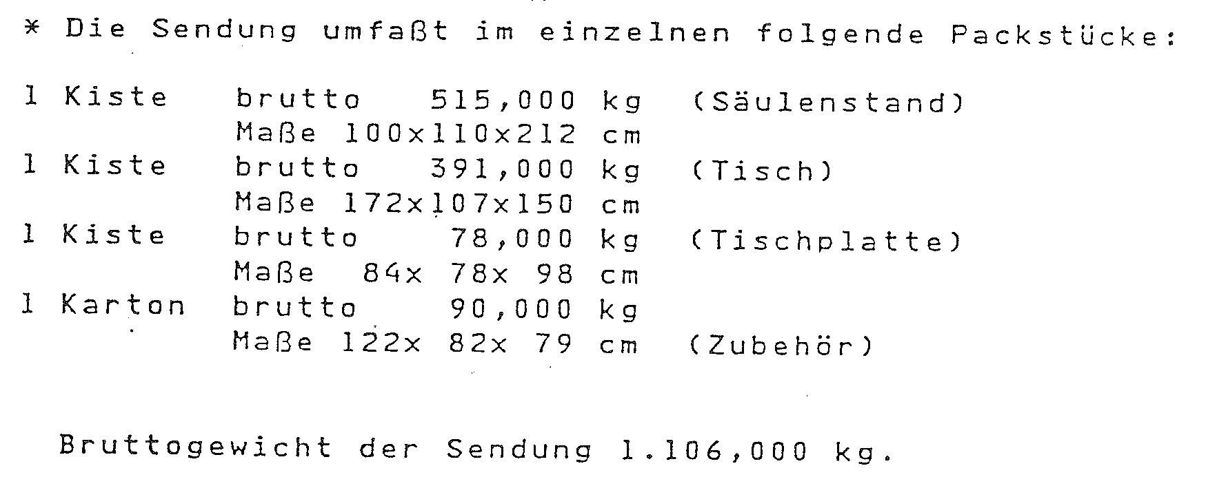
![]()
![]()
So we hauled almost a metric ton of SEM into our lab.
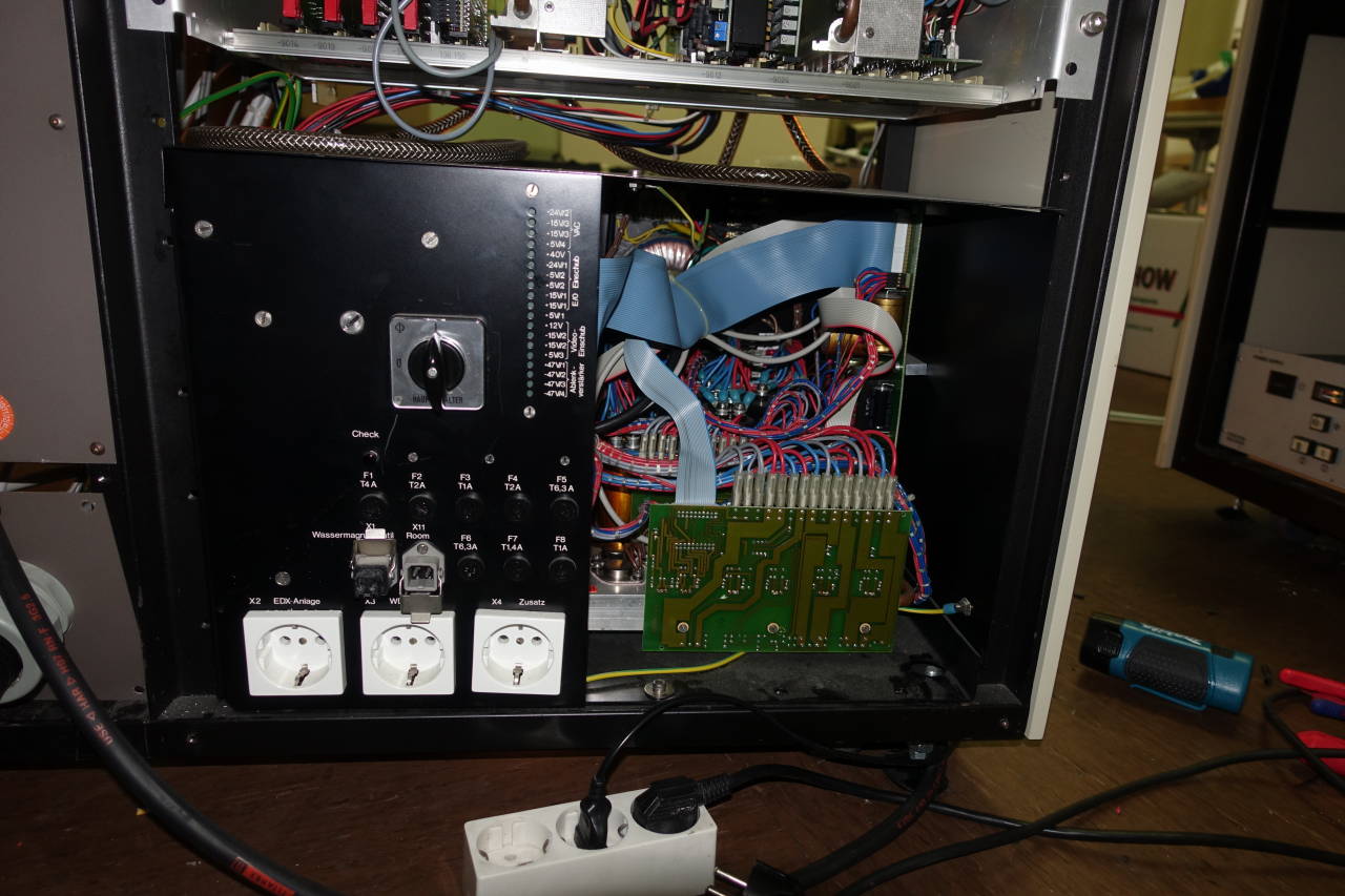
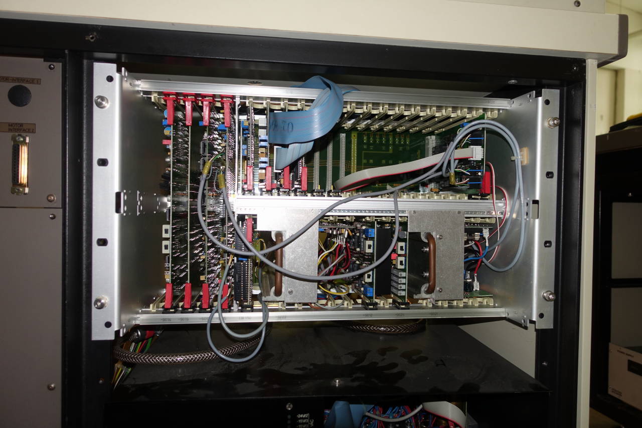
I beefed up my knowledge about Scanning Electron Microscopes. First of all, a well-known thread on mikrocontroller.net, a german forum about - well, everything containing microcontrollers - described a few details. First, the “digital” part of “DSM” means that, contrary to other devices from that age, most of the logic has been implemented in digital gates, mostly based on regular 74xx TTLs, with some microcontrollers here and there. The scan generator, raster amplification, video amplification is still analog, but at some point there’s an ADC that digitizes video data.
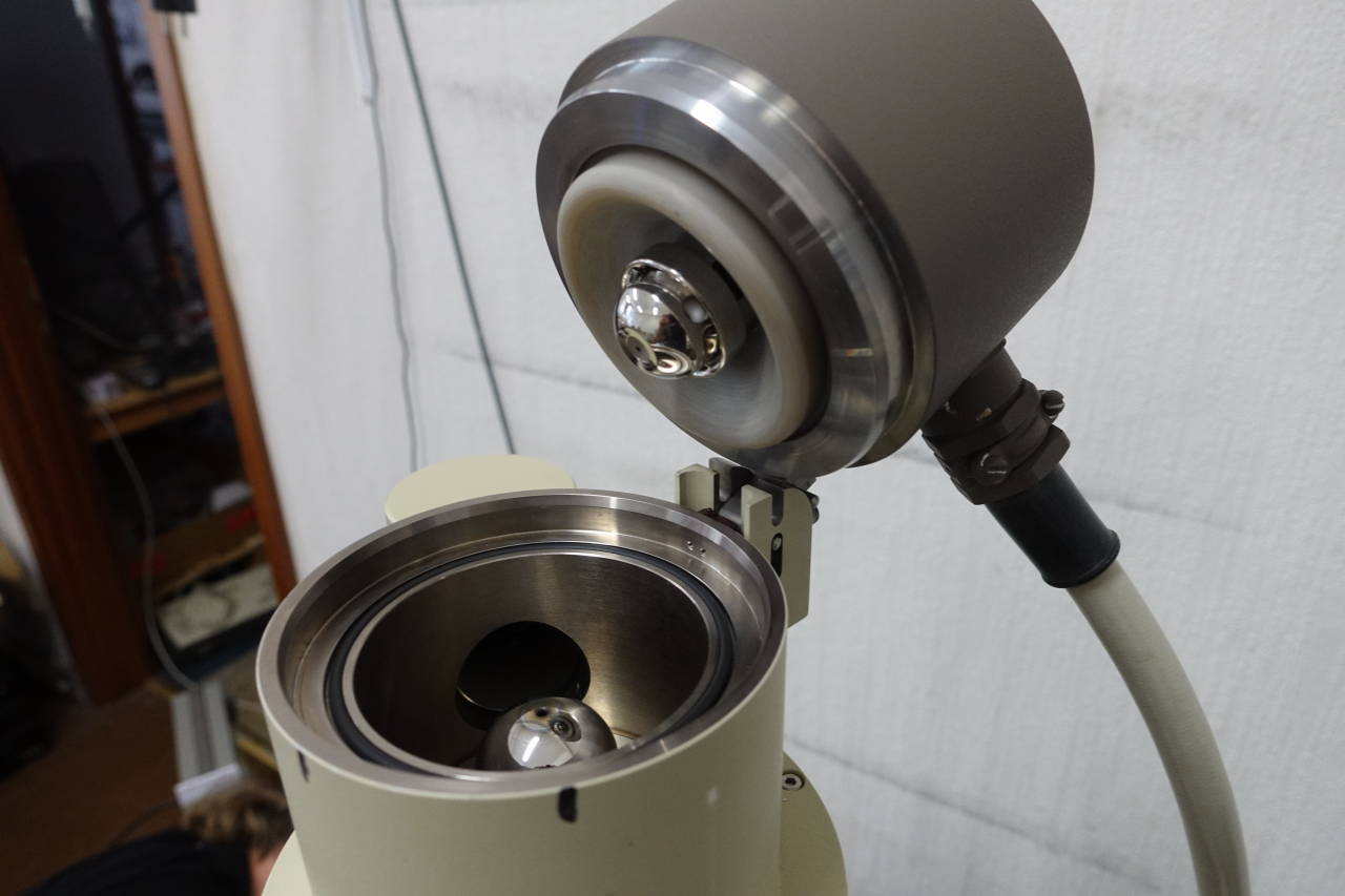
Also, this DSM-950 was a basic tungsten-filament one. The more fancy SEMs would either use LaB6 cathodes, or use a so-called field-emission cathode. While tungsten filaments have a limited lifetime of a few hundred hours, they are significantly more robust and also don’t require a very good vacuum. I’m mostly a software hacker, so I didn’t feel I’m up to the task of fixing a leaking vaccum. For reference, a Tungsten-based SEM needs a vacuum level of ~10-1Pa, a LaB6-based SEM around 10-4Pa, and a Field-emission gun around 10-5Pa. As you can imagine, the higher the vaccum, the more complicated the setup is. A Tungsten-filament seemed like a very nice “beginner’s” SEM to me.

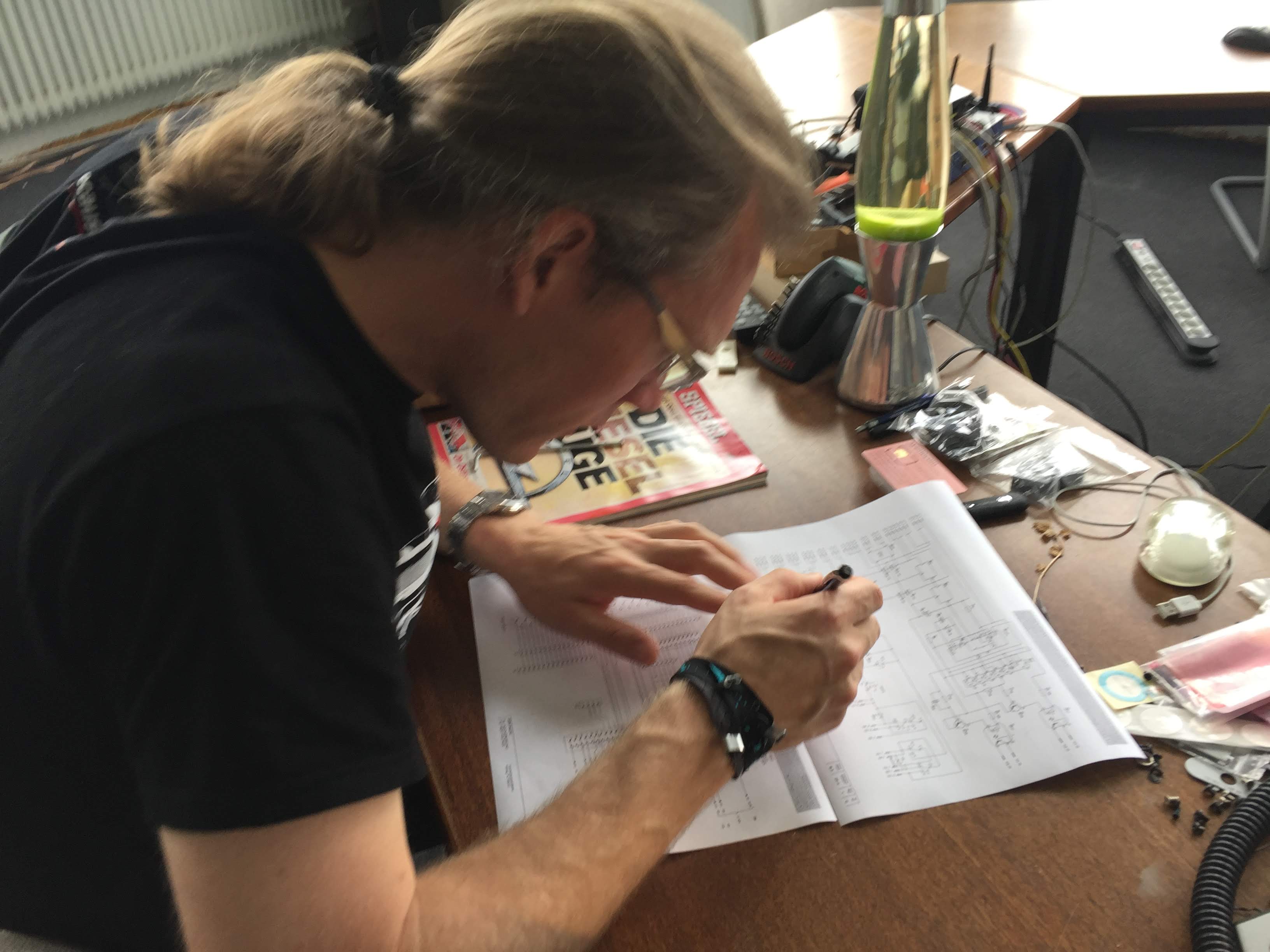
Next, schematics: I was able to obtain scanned schematics from different places; Zeiss still sells them on CD. As these schematics were made in the 80’s, they weren’t originally available in digital, but scanned in afterwards. the result is a relative disorganized, non-searchable PDF. But they were more or less complete schematics. No further “Service Manual” or adjustments notes though.
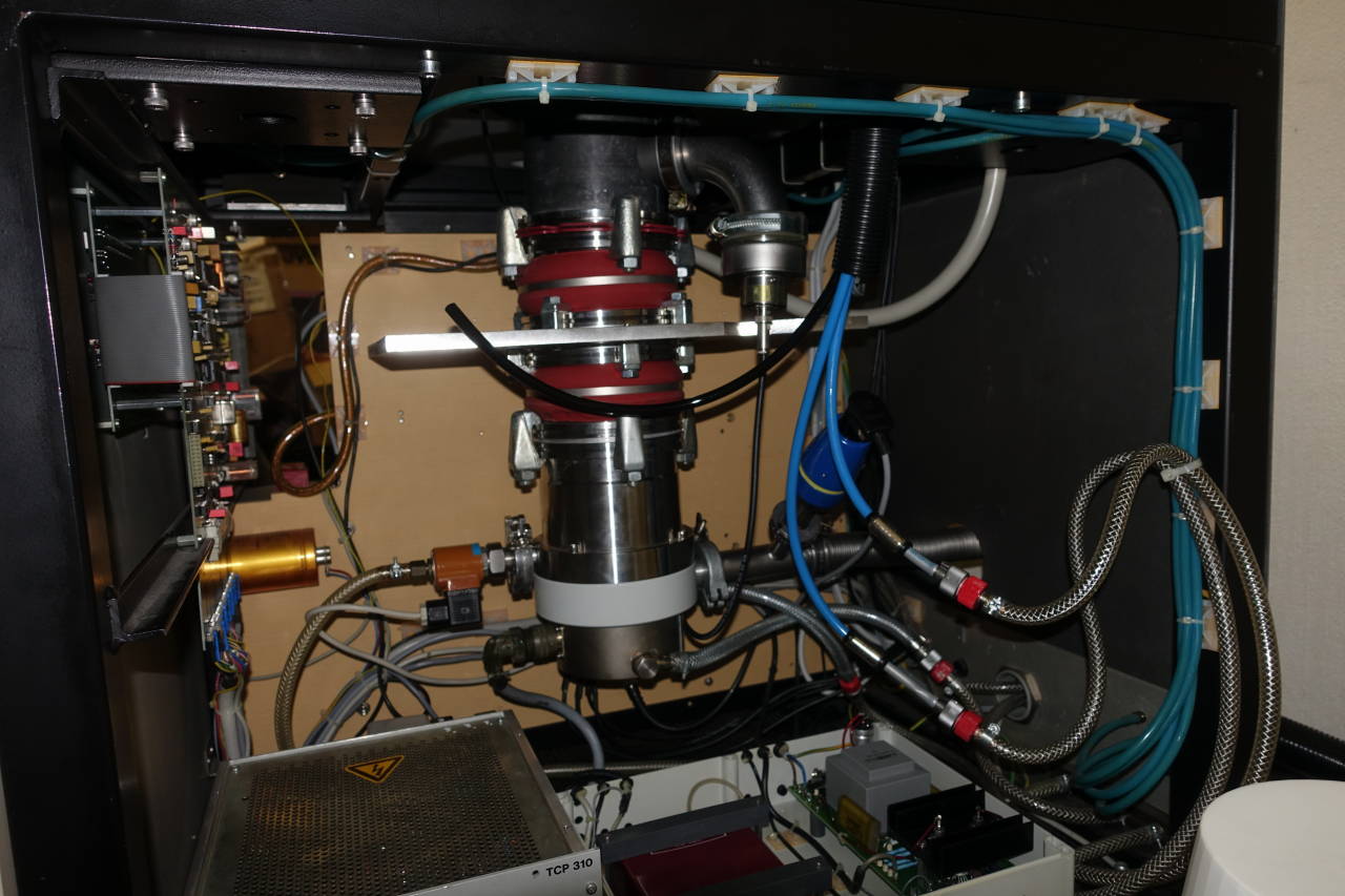
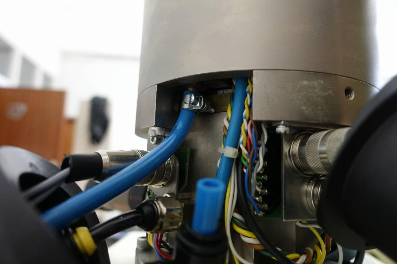
When we brought up the SEM, the first thing we needed to fix was the water cooling. Most parts of the device are water cooled - but, as you may know, water and electricity doesn’t mix very well. Some rusted spots (thankfully only outside) were an indicator that leaks were do be expected, but further investigation showed that apparently people had already tried to fix it a few times. We carefully tested the cooling system with compressed air, which at first horribly leaked out at many places. We replaced some of the fittings, and eventually it could maintain a stable pressure. We then connected it to an open-loop water system - basically we just connected it to a faucet - and that worked well enough. (Later we replaced this with a closed-loop system and a water tank as a radiator). The TDP of the SEM is specified as ~1.5 kW, so it’s not that excessive; in reality, a lot of the heat is radiated from the device already, and we’re usually getting nowhere the peak ratio. Ironically most of the power seems dissipated from the raster amplifiers when operating in low magnifications, and that’s not typically something where you operate the device in for a long time.
After that, it was time to power on the SEM. We toggled the main switch, and, lo and behold, there was… smoke. Magic smoke. Uh. We quickly determined that it was from the monochrome monitor; the DSM-950 has two CRT screens. Although we’re pretty sure we did not mix up the polarity of the power (we had to disconnect it for the transport), we couldn’t pinpoint the failure.
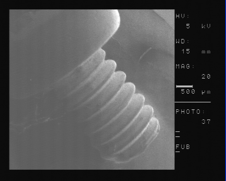
The second screen, an RGB monitor, can be used as output as well. After some more problems, some involving sparks (the high voltage coax wire for the scintillator - 10kV! - needed to be spliced, and that wasn’t high-voltage proof; oops), some not involving sparks (we mis-aligned the cathode gun safety switch so it never allowed the HV to be switched on), we finally got a picture!
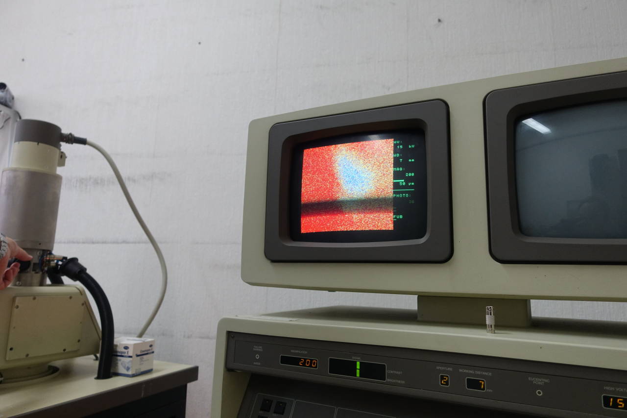
It was just really hard to make something out. Especially since none of us had ever used a SEM before. The color screen is 3-bit color, and only works for Slow Scan (more on that later), so it’s really hard to get the initial adjustments correct with just the color screen.
After some more debugging we declared the monochrome screen as fubar. And only after Ole was electrically shocked near the color CRT - turns out the main switch didn’t disconnect the screen’s live; oops again - we also declared the color screen as persona non grata. Luckily, the monochrome screen was driven with a regular 50Hz composite signal (though, as you can see, the interlacing was swapped sometimes…).
We had more fun with this SEM. For example, we built a digital capture adapter using an OpenVizsla, reverse-engineered the firmware to debug serial communication. We broke (off, literally) the BSE detector (and subsequently fixed it). But that’s another story for another day…