Probe Hacking, Part 1
The WhatsInside post from January was not an incidental post. It is actually snapshot of a much longer forensic investigation to find the ground truth behind some of the technology behind Tektronix’ scope accessories.
Pun aside - In October 2009, I’ve got a new scope, a Tektronix DPO4034. It’s a scope in the $8k range, so while not exactly low-cost, you don’t need a mortgage on your home to buy it. The raw specs are nice, but not awesome - 2.5GS/s, 350 MHz, 4 Channels, not much more than the $2k-range TDS2024 that I was using before. But while the TDS2024 has a sample depth of 2.5k, the DPO4034 has an awesome sample depth of 10M! That means that you can actually sample once, and then spend time on analyzing this measurement. Or store the measurement, and do proper postprocessing. Suddenly, the scope stops being a multimeter and starts being a universal all-purpose tool. The DPO-series all have a number of software options, delivered as small dongles that you can stick into some slots in the scope, that enable certain software features - features like UART, SPI, I2C, CAN and even USB protocol decoding. The scope runs ppc44x-Linux, but that’s really just for the frontend. The backend is a number of Tektronix ASICs, that manage the high-speed data acquisition and visualization.
Of course, the analog part is as important - or even more important - than the digital part. The scope offers a selectable input impedance of 1MΩ and 50Ω, and can supply power to “intelligent” probes like the TAP1500.
A low-end scope usually uses passive probes. A passive probe is usually cheap (<$100), and often uses an attenuation circuit (basically a voltage divider) to lower the total input impedance. The advantage of this is that the probed circuit is much less affected, but the disadvantage is that the signal will be attenuated by the same factor, usually “10x”. Due to the high impedance to the scope, the signal is susceptible to noise. If you ever used a passive probe in a EMI-poluted area, you know what I’m talking about. Proper ground clips make an incredible difference. My DPO4034 came with 4 P6139A probes. They come with 3 different ways of attaching to ground - and believe me, it makes an awesome difference. Obviously, the ground path is as important as the signal path itself.
You can easily spend more money on probes than on a scope, if you buy active probes. They have an integrated amplifier, usually direct inside the probe tip. See bunnie’s NTW post for a picture of such a probe head. There are even some probes in the $25k range! Active probes use a 50Ω output impedence to the scope - thus the signal path from the probe to the scope is much less affected by EMI. Active probes, hence the name, need power. The mid-range and higher scopes usually have support for such probes, and have extended connectors which carry power and control signals (like “offset”), next to the signal itself (usually on BNC).
Now, I’m cheap. I don’t have the money to buy a >$1k probe, and still I want to have the joy seeing traces that actually look like the darn SPICE simulations. So I went to eBay, and bought a P6245. The P6245 implements the TekProbe BNC standard - a slightly extended BNC plug that carries +/-15V, +/-5V, control and data. This doesn’t directly fit into the DPO4034, since that one implements the newer TekVPI (please read this document if you want to understand the rest of this post) standard. There is an adapter, though, the TPA-BNC. I’ve bought it used, but working (as far as the description goes) on eBay, for $300, with the seller giving a “7 days return right”, since the seller “take[s] customer satisfaction seriously”. Well, except that the thing didn’t work. Whenever plugged into the scope, the LED would light up, then go dark, and the Scope would display a “Probe Error” message. At first I’ve thought that this might be just because I didn’t had a probe connected (the P6245 arrived much later). I’ve contacted the seller, and he responded with:
Hi, I have to sell before you tested, TCP-BNC can work, these adapters on the electrostatic demanding, in operations to bring static belt. give you trouble, I'm terribly sorry, If you do not want this probe, but also back to me, I give you back 200$,How do you think
That’s not what I call “serious customer satisfaction”. Unfortunately, the 7 days inspection period was already over. Great, I had a broken device, and paid $300 for it, with the seller claiming that I had destroyed it due to ESD.
DISCLAIMER: Don’t mess with your scope or anything that (directly) attaches to the scope. You will lose all warranty. You might destroy not only your probe/adapter, but also your scope. Is that really worth saving some bucks by doing the repair at home?
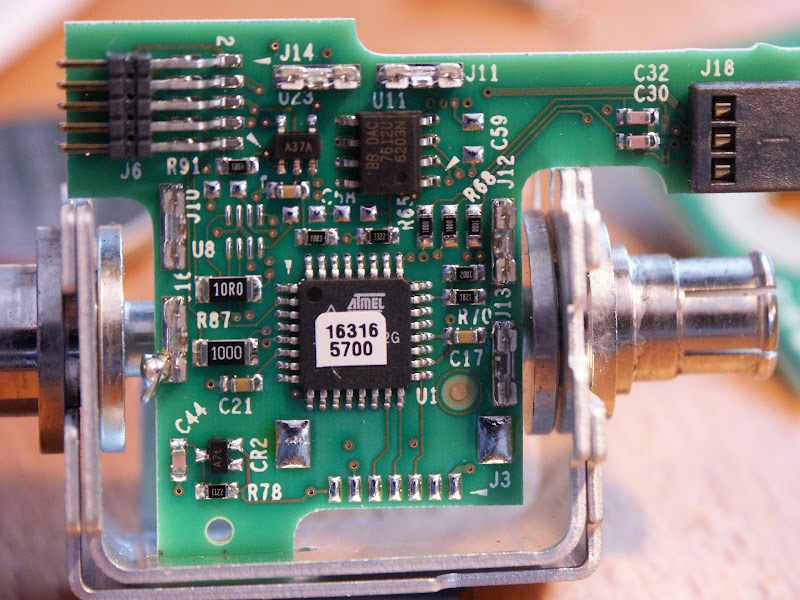
Then the probe arrived, and still, I got this probe error. Damn. We opened the TPA-BNC, and tried to understand the reason for the mis-behaving. Fortunately, the ATmega8 was not locked, so we could read out the firmware.
As said, the failure behavior was that the LED on the adapter would quickly light up, go dark again, and then the scope would display the error message. We sniffed the communication between the scope and the adapter (it’s I2C, btw). It looked like:
A0, 00,
A1, 05 03 31 3C 05 37 14 02 54 50 41 2D 42 4E 43 00 42 30 31 33 35 32 36 00 01 03 05 03 10 57 56 02 56 06 57 00 00 20 40 06 10 00 00 80 3F 06 1A 00 00 C8 43 08 85 01 00 01 02 03 04 BB,
7C, 02 02,
7D, 04 04 01 01,
7D, 03 01 01,
7D, 02 00,
7D, 02 00,
First, the adapter responds to A0/A1 reads, like a traditional I2C eeprom. It looks like all of the “smart” probes have an eeprom inside, that tell the scope what kind of probe is connected. The probe responds with a config block, including the TPA-BNC serial number. We couldn’t make much sense out of the rest - it’s probably an error message, but it doesn’t look like a specific error code.
We reversed the hardware connections a bit - here’s a block diagram I’ve built:
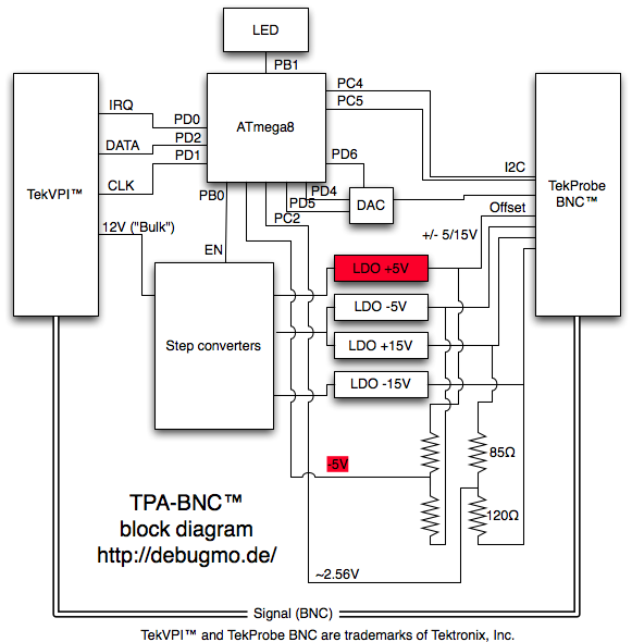
Noticing that the LED was blinking a single time, we tried finding code paths that lead to this behavior, by looking at references to PB1. The LED is accessed whenever the probe power is enabled - there is a master switch for the stepup/stepdown converters, connected to PB0. The algorithm basically looked like:
- enable LED
- enable power
- measure ADC values until they reach a specific range, or timeout if not
- if success: leave LED enabled, read eeprom, configure DAC
- otherwise: turn off LED
This piece of code apparently checks the power board to work correctly. There is an interesting question: The voltages are symmetrical, and the ATmega8 can only measure between GND and the Vref-pin (which is +5V, here). How can they measure the negative voltages? A hint for this is that they get away with 2 ADCs - they have a voltage divider between -15V and +15V that will result in a voltage of +2.5V (if both voltages are supplied correctly), and -15V, +15V or 0V if not. The same circuit (just with a different voltage divider) is used for +5V/-5V. The behavior we’ve been seeing matched more or less what we would expect from the source if the ADC never got into the right range.
We measured the output voltage of the step converters, and they were all in the valid range - about +/-16V and +/-6V. However, measuring after the linear regulators, we figured out that the +5V were missing. Looking at the linear regulator, in a SOT23 package, it only had a single marking “PGVI”. Google helps - it’s a TP73001 adjustable, positive low-dropout linear regulator. Luckily, we had a single one of them in stock (talk about luck…), so we replaced it. We plugged the adapter back into the scope, and voila - no more errors!
So, stupid eBay seller: This adapter wasn’t broken because I touched it without an Anti-ESD-belt, but because someone likely shortcut the +5V supply to the probe. It was DOA, and you probably knew this. You scammed me (at least that’s how I feel).
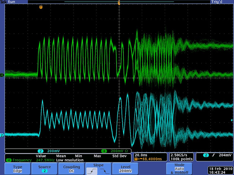
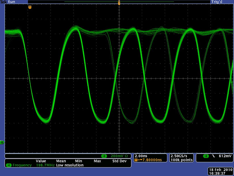
We plugged in the active probe, and hell yeah, it worked! The scope automatically switched to 50Ω input and 10X attenuation (meaning that the scope could read the probe ID data from the probe’s I2C eeprom), and the probe was properly displayed in the “about” menu.
On this picture, you can see the difference between an ordinary, passive probe (with a normal GND connection), versus the active probe. The signal is a USB 2.0 highspeed SOF.
Isn’t it nice?
Next time you’ll see how we connectedhacked a P7350 (no, not that one…) to this scope.