What's Inside: Tektronix DPO5034
Expectations
This post is about a teardown of an DPO5000 oscilloscope (DPO5034). This is a 2011, mid-range, Windows-based Tektronix oscilloscope. List price is $12.000, but eBay has them - used - down to $5500 or so if you're lucky. This particular model is a 350MHz, 5Gs/s model without MSO functionality (adding 16 digital channels, a "poor man's logic analyzer" -even though it rather *makes* you poor when buying it, since it's pretty expensive). The higher end models in that series support up to 2GHz bandwidth, 10GS/s (albeit only on two channels in an interleaving configuration) and support the "MSO" function out of the box. The top-end model (MSO5204) has a list price of $28.700. What do we expect from a teardown of an oscilloscope? http://www.microwavejournal.com/articles/10796-time-is-on-our-side-oscilloscopes-for-microwave-engineering has a block diagram that we somehow expect to find in our scope:
 But before the signal gets here, it will first go through the analog frontend. But guess what - I've opened up that one, too!
Analog Frontend
The analog frontend is a seperate board that sits in the front of the oscilloscope (behind the frontpanel).
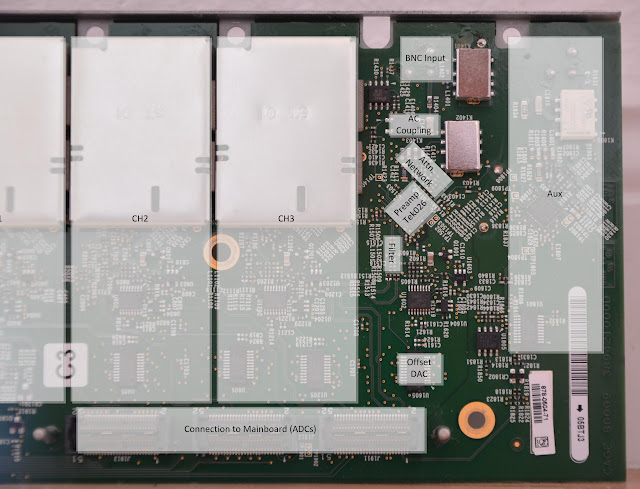
The signal enters the oscilloscope on the BNC connectors on the front of the scope. Additionally to the signal connection, there are data connections and power supplies for the probe - called TekVPI. Those data and power connections are handled by the front panel, which I did not photograph. It’s mostly 12V plus I2C and an interrupt pin.
The frontend attenuates/amplifies the signal and converts it to a 50-Ohm differential signal suitable for the ADC. All the low-noise operation happens in this path of the scope. The analog frontend consists of 4 channels, each with an optional 50-Ohm coupling or optional AC-coupling, a passive (RC-based) attenuation circuit with selectable signal paths, an active pre-amplifier with a Tektronix-ASIC (internally called “Tek026” though the package mark doesn’t mention this part number) and a bandwidth-limiting lowpass filter (implemented as a differential pi-Filter). Higher-bandwidth scopes (1 GHz and 2 GHz models) have an additional second-pass pre-amp called “Hfd144”, which is not present on my 350 MHz scope.
Additionally there is the “Aux” channel, which is good for triggering only. On the MDO4000-Series, which use the same architecture (but a different Analog Frontend) as the DPO5000-Series, instead of the Aux channel, there is a dedicated RF channel.
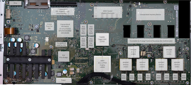
Trigger Asic
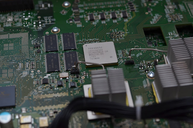
This oscilloscope uses the Tek005 trigger IC, again a Tektronix-specific ASIC. Triggering must be done on the analog signal in order to achieve a sub-sample trigger timing, which is required for things like equivalent-time (ET) sampling. (Equivalent Time sampling is widely explained on the internet, however there is one bit of “magic sauce” that’s usually missing from the explanation: The information on how to re-align the different samples with each other. The answer is that there is a special circuit in an oscilloscope called “timebase interpolator”, that can establish the exact trigger point between two ADC samples. For example, if the oscilloscope supports sampling the analog signal with a sample rate of 5 GS/s, there is an ADC value for every 200ps. If the triggering would be digital, this would be the trigger resolution. Since triggering, at least for simple trigger modes like “Edge”, is done on the analog signal, the timebase interpolator can often pinpoint the trigger point down to 10ps or less. By obtaining multiple traces, all shifted by a random sub-cycle delay, a more accurate waveform can be assembled.)
The trigger ASIC also interfaces to the “slow” MT48LC16M16A2-7E SDRAM (8 chips total, total 256 MByte, or 128 MSamples), which is used for the MSO feature. The total theoretical memory bandwidth is 8 x 16 x 133 Mhz, or 2128 MByte/s, easily covering 500 MSamples/s (each sample being 16 bit). So the MSO feature is actually implemented in the Trigger IC. The “MagniVu” feature, which allows capturing with up to 16.5 GSamples/s, but only up to 10k points, is also implemented directly in this IC.
ADC
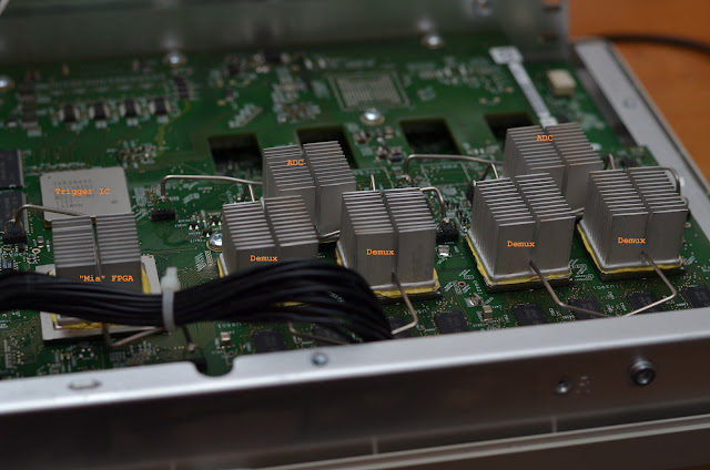
The Tektronix DPO5000-Series supports a sample rate of 5 GS/s when all channels are enabled. That means that there is a total sampling capacity of 20 GS/s on this model - distributed to the four analog channels. Some models (the 1 GHz and 2 GHz models) allow combining the sample rate of two channels into a single channel, thereby allowing sampling up to two channels at 10 GS/s. It must be noted that no different ADC configuration is used for these models. The 20 GS/s are divided over two ADC chips. Each ADC outputs 10 Gbyte/s of data.
Demux
The heart of the oscillscope is a device called “demux”. A demux connects the ADCs with the Acquisition Memory - in the DPO5000, there are 4 chips for each of the 4 demux. The chips are marked “D9LHT”, and Micron’s FBGA part decoder tells us that these are MT47H64M16HR-25E:H - 1 Gbit of DDR2-800 SDRAM. That’s 512 Mbyte per demux, with a theoretical bandwidth of 800 Mhz x 16 Bits x 4 Chips / 8 Bits = 6.4 Gbyte/s - barely enough to stream the 5GS/s (=5Gbyte/s) to memory. So the main task for the demux is to store the incoming data from the ADCs to memory.
But the demux also includes a DSP that can provide FIR filtering and other general-purpose data processing on the buffers. This is used for the MDO4000-models, which feature an RF data path, where the Demux-pair (two of the four available are used for the RF path, the other two are used for the analog channels) is used to demodulate the incoming time-domain samples into I and Q, and also transforms them into frequency-domain for a spectrum-analyzer display.
Additional data processing is also used for the “Enhanced Bandwidth”-feature, where DSP filters are used to fix a probe’s frequency response - the software includes tables for various probes, sometimes even in combination with a specific probe solder-down connector (one example being “P7380 Right-Angle Flex_25X.flt”)! This is mostly relevant for the ultra-high bandwidth probes, and thus not really relevant to the midrange scopes.
The demux also contains the “FastAcq” or “DPO” feature, which is basically an embedded framebuffer with 21-bit counters per pixel. http://www.tek.com/document/technical-brief/advanced-statistical-analysis-using-waveform-database-acquisition has some more technical details on the DPO/FastAcq feature.
Display
The demuxes communicate with an FPGA called “Mia”, which merges the outputs of the four channels, and then generates the actual pixel data that is displayed on the screen. The data is transmitted over PCI Express to the integrated PC for display on the integrated touch-screen.
Comparing DPO5000 with the DPO4000B and MDO4000
It’s interesting to compare the DPO5000 oscilloscope with a second-gen DPO4000 (called “DPO4000B”-Series) or with the MDO4000. EEVBlog has a nice teardown of a MDO4000 here. The obvious part is that the DPO4000-series uses a Linux-based firmware instead of a Windows-based firmware. The DPO5000 comes with an integrated PC that connects to the rest of the scope via a PCI-Express link to “Mia” (via a PLX PCI-Express bridge). The DPO4000 does not have this PC (nor the PCIe bridge) - instead, it has an on-board PowerPC processor that interfaces to Mia, and a few support peripherals (Ethernet Phy, Flash, RAM).
DPO4000 and DPO5000 share the same front-panel, though in slightly different configurations (the DPO4000 has a few buttons around the screen, whereas the DPO5000 has a touch-screen; the MDO4000 additionally has the numeric keypad on the right).
The lower-bandwidth (<1 GHz) DPO4000(B)-Series scopes only support 2.5 GS/s on all four channels - they only have one ADC chip (and two instead of four demuxes). On the MDO4000-Series, which has the dedicated RF-Input additionally to the analog channels, 10 GS/s, i.e. half of the ADC power, is dedicated to the RF signal. That is why even the higher-bandwidth MDO4000-Models can only capture 5 GS/s on two channels - they have the same ADC configuration as the DPO5000, but already use half of them for RF.
"You get what you pay for"
The more high end a scope is, the more additional features can be enabled with purchased “Options”. This is not only true for Tektronix scopes, it’s also true for most other test instruments. The reversed logic of this is that the scope itself is more capable, at least in terms of what the hardware can do, than what’s exposed in the firmware. For example, we figured out that this scope has 512 Mbyte of RAM per demux. If we assume “one channel is one demux” configuration (which is a bit too simplified, but not exactly wrong), that means that the scope could - in theory - have a capture depth of 512MSamples. By default, the scope does have a maximum of 12.5 Msamples. Even if we take into account that the user might display up to 4 reference waveforms and 4 math waveforms, and the demux may also store the rasterizer (display) data, that’s still more than 128 Mbyte per channel, a huge difference to the 12.5 Msamples that the scope offers.
The answer is easy - there’s an option, called “10RL”, which, according to a price list, goes for a whopping 7920 Euro, which bumps up the sample depth to 125 Msamples - without a hardware change, of course, just by entering a software key. I’d rather skip the discussion about how you pay to use the hardware that you already bought… Ethically simpler is the discussion about protocol decoder options - for example the “SR-COMP” option that allows you to decode and trigger on RS232 signals that goes for 1480 Euro. That’s simply software that’s shipped with your scope, but not enabled - which I understand: development of this software costs money, so it makes sense to have only people pay for the development who are actually using the software (whether that price is appropriate though can be debated, but should not be an excuse for pirating that feature).
However, that’s something else from simply limiting the amount of capture memory - though even in that case you could argue that they may “subsidize” the cost of DRAM. But 7920 Euro for a roughly Gbyte worth of RAM? Last time I’ve checked a Gbyte of RAM was about 20 Euro - remember, we’re talking about standard DDR2 memory, not anything high-speed or custom.
I feel similarly about the “MSOE” option - which enables the use of the existing MSO feature. But either way, I don’t want to discuss Tektronix’s business model here. If I wouldn’t like it, I wouldn’t have bought their hardware.
Bandwidth
A much simpler topic then becomes the bandwidth limitation. Tektronix doesn’t sell a bandwidth upgrade for this scope (unlike for some other series, like the DPO3000), which indicates that bandwidth is indeed a physical limitation, not a software setting. We’ve seen scope bandwidth hacks before (http://www.instructables.com/id/Hacking-the-Rigol-DS1052E-Oscilloscope-with-Linux/), where the bandwidth limit was set by a software-controllable filter. Looking at the analog frontend again, we see a suspicious looking circuit:
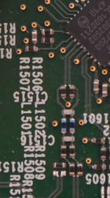
Would this be a first-order differential low-pass filter? In fact, in bypassing this circuit (and thus removing the anti-alias filter - please know what you’re doing, and of course you will loose all warranties, and every time you do this an engineer will die in heaven), suddenly frequencies above 350 MHz become much happier and will make it to the ADCs: (left is an unmodified channel, right is a modified one)
 |
 |
(This is Gen1 SATA, hence a fundamental frequency of 750 MHz. With a bit of postprocessing, I could even capture Gen1 PCIe with its 1.25 GHz fundamental and decode the bits in software.)
This is of course not the same as an actual instrument with that bandwidth. As mentioned, the 1 GHz+ models have an additional pre-amplifier stage, and of course a well-defined bandwidth limitation. I’m betting that my hacked up channel doesn’t have a flat response up to the maximum anymore, but I lack the equipment to actually characterize the behavior.
Mysteries Left
There are a few mysteries left.- What’s the unpopulated device at the top right on the mainboard?
- Why is the MSO acquisition RAM twice as big and twice as fast as required by the specs?
- What the hell did they think when they designed the user interface of the frontpanel? (I could rant about this for hours. The DPO4000’s UI is designed for this frontpanel, and “makes sense”. The DPO7000 (and all higher end models) have a slightly larger front panel, which for example allows directly changing the trigger source. The DPO5000, however, has the UI logic of the DPO7000, but the frontpanel of the DPO4000. This combination makes no sense. Barely a function can be achieved without using the touchscreen. On the other hand, there are countless buttons (when was the last time you - intentionally - pressed “Autoset”? Default setup? “R”? “Play/Pause”? Why are there two - lighted! - dedicated buttons for “Coarse” and “Fine”, but no dedicated button for switching between “offset” and “position”? Why is there a dedicated “intensity” button? This could go on for a while.) Please, Tektronix, either allow customization of Frontpanel button to UI mapping, or just have someone use this scope for a day and then reimplement the mapping.)